 |
| The completed project. |
<tap…tap…> <Is this thing on?… testing 1,2...>
It’s been a long time since I’ve posted anything, indeed, I thought any future posts would go to my photo blog which has also been sitting idle. Since this is not a photo post, I figured this was as good a place as any... Guess I haven’t had much to say. Retired life is excellent!
Way back in the day I started out as an Avionics Technician in the Navy. I grew up reading Popular Electronics and occasionally building one of their projects, so it was a natural thing. While I moved on into the computer world eventually, I still have that fascination with things electrical. Also being a musician of sorts, it was only natural I fell into this project.
The Fender 5F6A Bassman amplifier made from 1958 to 1960 had quite the influence on popular music - both country and rock. While intended as an amp for bass guitar, its biggest influence has been as a straight guitar amp. An original ’59 Bassman goes in the neighborhood of $10,000 or so, putting it out of range of the average guitarist. This was the amplifier circuit that Jim Marshall based (with modifications) his original Marshall JTM 45 on.
Fender sells reissues which while using the same circuit design are built using modern techniques on printed circuit boards. While no doubt a fine amplifier, dinosaurs like myself long for the old school hand wired amps. Fortunately, there are several companies that have assembled kits to the old specifications. One of these companies is Mojotone, and I recently bought a 5F6A kit from them. I thought I’d share the construction process.
The short version - I built one of my dream guitar amplifiers. It was fun. It sounds great! If you want all of the gory technical details, continue reading.
I went with Mojotone because they assemble a quality kit based on the original Fender schematic and layout documents. There are a few modifications - the old two wire power with a ground switch is replaced with a modern 3 wire power cord and updated switches, and the grounding capacitor in the original circuit is deleted since it is potentially dangerous and doesn’t do anything with the modern power cord.
 |
| The speakers installed. The wiring will get shortened after testing. |
Mojotone sells the kit as a chassis only, you have to order the cabinet and speakers separately. As the cabinet can be custom made and covered to your specification this makes perfect sense. I ordered the kit and cabinet from them in the first week of December. I received the cabinet in a couple days, but the kit was back ordered. This was clear on their web site, not a surprise. I ordered four Jensen P10R speakers locally from Antique Electronics Supply. I went with the P10Rs partly because that was the original speaker used in the Fender amps, but mostly because I really like the sound of them. I went ahead and installed and wired the speakers in the cabinet as that was the most convenient way to store them until the kit arrived.
 |
| The kit is well packaged and complete. |
Mojotone said back orders for kits were 4 to 6 weeks, and promptly four weeks later it was delivered. While the kit has everything you need to build out to the schematic, I wanted to make a couple of changes. As anyone who has worked in electronics can tell you, the published schematic is a starting point and not always what was shipped. Fender changed a couple of things along the way and I wanted my amp to reflect that. For those interested the changes I did were to use linear potentiometers for the volume controls instead of audio taper, changed the tone slope resistor from 56kΩ to 100kΩ, the bass capacitor from .02 to .1 ufd and the phase inverter tail resistor from 10kΩ to 6.8kΩ. In addition, instead of using a 5kΩ pot for the presence control, Fender used a 25kΩ linear pot bypassed with a 4.7kΩ resistor. Because of the magic of electronics, this meant that the AC signal saw a 3.9kΩ log taper pot (through a capacitor) to ground while DC saw 4.7kΩ. Finally, I wanted to add a Master Volume control and ground the circuit directly to the chassis or brass ground plate like Fender did back in the day. Mojotone provides ground tabs to be connected to the transformer mounting bolts since chassis grounding requires a heavy duty soldering iron that most people don’t need in addition to one suitable for electronics. I also bought a matched set of 5881 tubes to use instead of the more popular 6L6CG tubes provided by Mojotone.
 |
| Basic chassis wiring |
 |
| Transformers and filter caps |
After verifying the kit was complete, I started by getting the chassis as complete as possible. This meant installing the transformers and choke, tube sockets, and some of the front panel. I also prepared the grounding points by removing the plating with a Dremel tool and tinning the spots with solder to make it easier once I was ready to attach the grounds. I went ahead and assembled the filter capacitor board and installed the filter caps in the pan on the outside of the chassis. Fender grounded the filter caps directly to the pan in the ’50’s, while Mojotone runs the ground to the board with the signal grounds. I went ahead and ran the ground to the chassis point with the AC grounds to keep them separated from the signal path. I also cleaned and prepped the grounding points on the brass plate I added under the controls and tinned those points as well. Finally I installed those components that mounted to the tube sockets and ran the power and output transformer wires where possible. I ran the heater power to the pilot light socket, but didn’t run the heater wiring since it would get in the way. By the end of day one most of the chassis was complete.
 |
| The guts. |
On day two I set the chassis aside and populated the eyelet board with components. This is a pretty straight forward process made a little more challenging by the resistor leads being just barely long enough - the made them longer in the ’50’s. Then I flipped the board over and ran the wires required underneath the board and soldering everything in place. I took the time to read the wiring with an ohmmeter to make sure it was correct. It’s pretty tedious to have to take the board out once it’s wired into the chassis. Finally I attached the wires for the tube sockets and front panel controls. At this point I took a long break, coming back later to verify everything.
 |
| The completed chassis. |
Once I was happy with the board I went ahead and installed the controls in the chassis and proceeded to install the board. Finally I ran the heater wiring to all the tube sockets and installed the power cable. As tempting as it was to power up at this point, I knew better and figured the next morning I would check everything while I was fresh before starting to test.
 |
| The testing begins... |
All rested up, I inspected the assembled amp again for obvious problems, and with the ohmmeter made sure ground was connected to ground and power was connected correctly. With no tubes installed I powered it up and checked the filament voltages and the bias supply voltage both of which were unsurprisingly high. This amp was designed when wall voltage was generally around 110, so everything is a little hot, though still within tolerable limits. (I later put the amp on a variable transformer and set it for the filament voltage of 6.3 volts. The input voltage was 111.5v. Normal wall voltage around here is about 121.5 and I've seen it as high as 123.6.) Next I installed the rectifier tube and checked the DC voltage at the Standby switch. This looked good so it was time for the fun to begin...
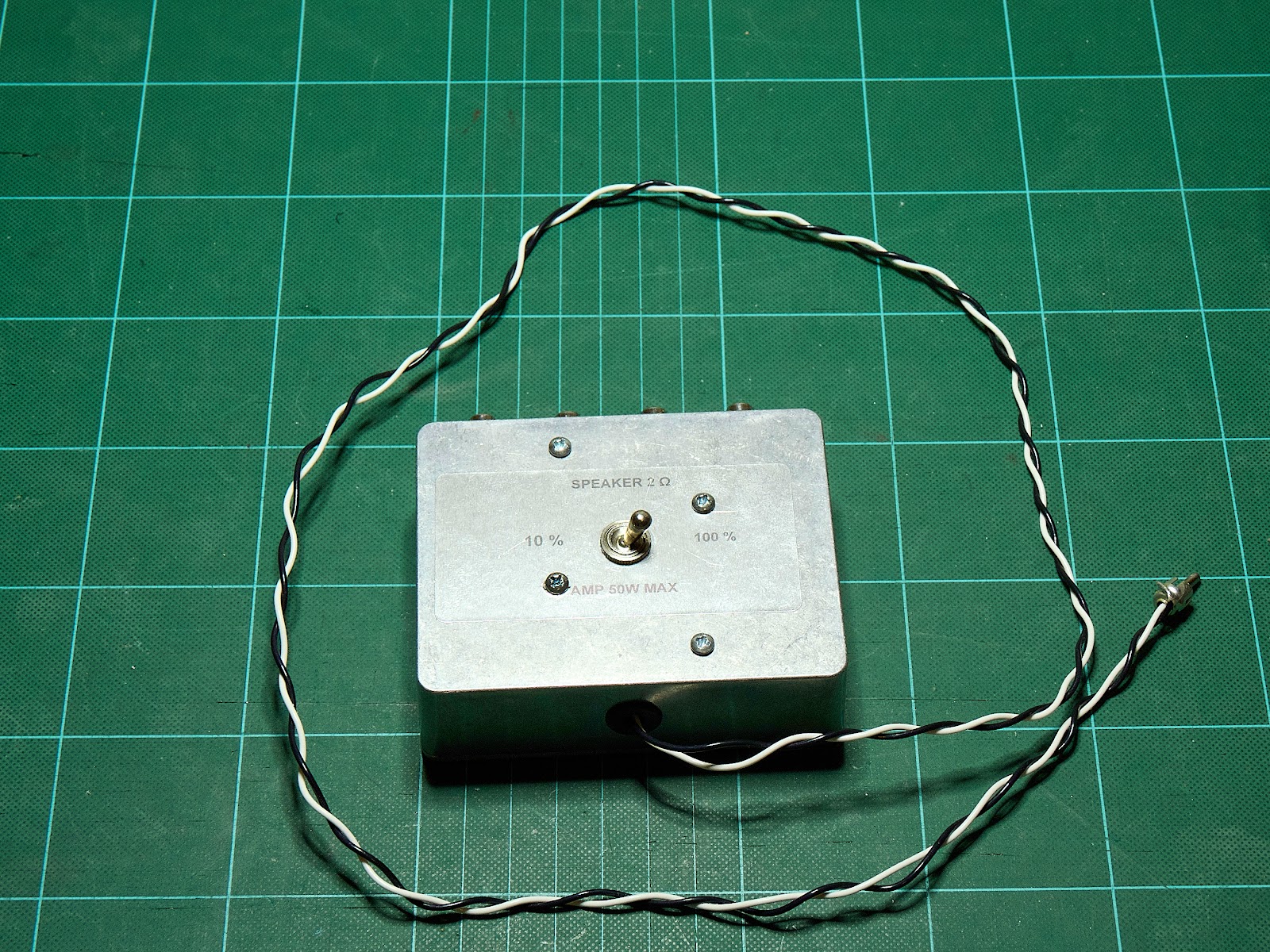 |
| Reduces the power by 90%. |
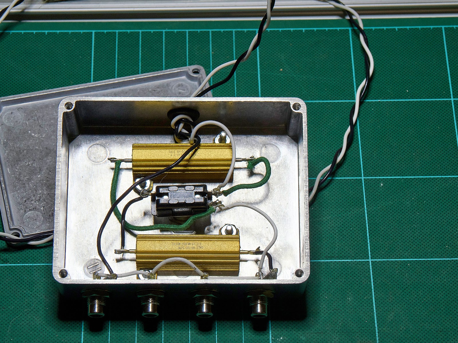 |
| Makes it the volume of a 5 watt Champ. |
 |
| Mostly done, but I hadn't shortened the speaker wires, yet. |
Some resources I used for this project -
Vendors:
Mojotone - Supplier of amplifier and guitar parts, cabinets, speakers, kits... Very responsive and good support. There are other quality kit suppliers out there, but I've been happy with Mojotone. Free shipping for orders over $99, but shipping is a bit high on small parts orders.
Antique Electronics Supply - My local source for components. Also matched power tubes. While they are on the other side of town from me, it's actually quicker and cheaper for me to order online from them. Postage on small parts orders is less the the cost of gas for me to drive there.
Mouser Electronics - Excellent supplier of components. I think they have everything.
Stewmac - Primarily a luthier supply house, they also handle some electronics.
Web information:
Rob Robinette's Web Site - A gold mine of information on tube amplifiers.
Youtube:
Psionic Audio - Amplifier repair in Memphis done right. Lot's of good information.
Uncle Doug - Lots of neat amplifier restoration videos.
Millstap - This guy has an original '59 and '60 Fender Bassman, and posted detailed videos on how the amps were actually constructed as well as detailing some of the required maintenance on old amps.